
11-15-2011, 05:42 PM
|
|
Member
|
|
Join Date: Jan 2011
Location: Blackburn UK
Posts: 425
|
|
Ive been reminded that I hadnt finished off this post on the 5L40-E teardown, so here goes. Picking up from where I left off above, starting with the disassembly of the main hydraulic block.....
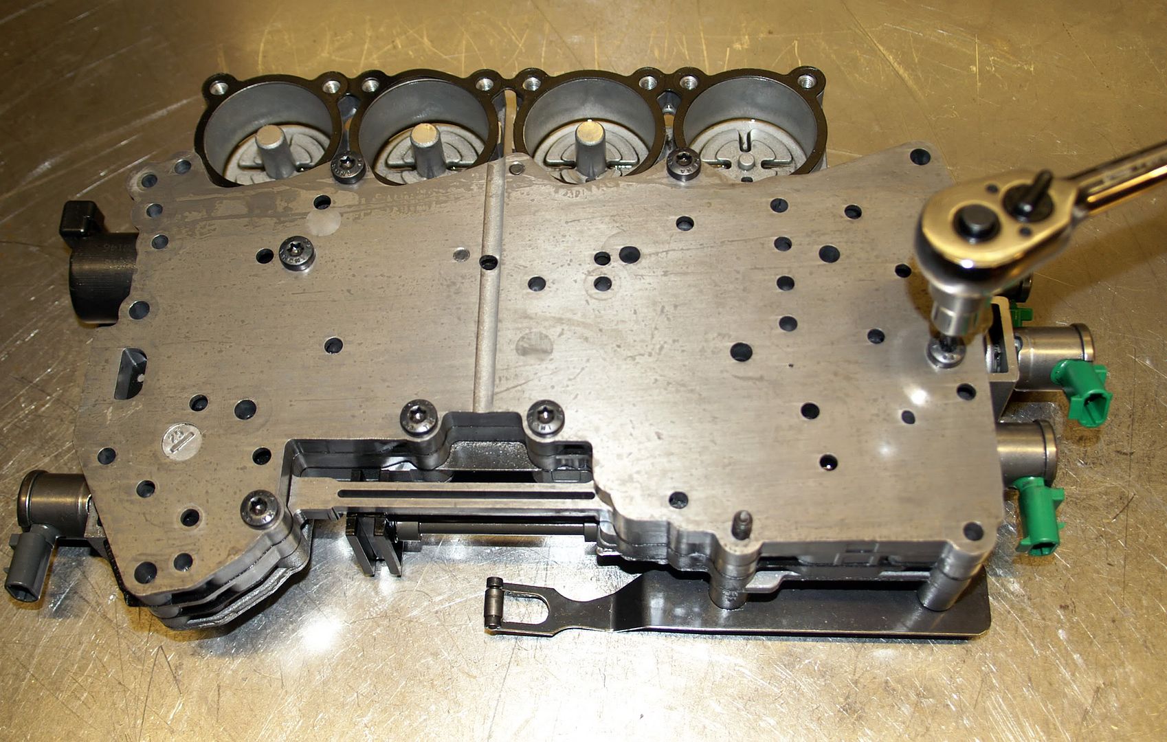
Working from the top side, the four accumulators are removed first. The accumulators are used as shock absorbers to control the feel of each upshift - each of the four upshifts having its own accumulator for the oncoming clutch :
2nd clutch accumulator = 1-2 upshift
Intermediate clutch accumulator = 2-3 upshift
Direct clutch accumulator = 3-4 upshift
Overdrive clutch accumulator = 4-5 upshift
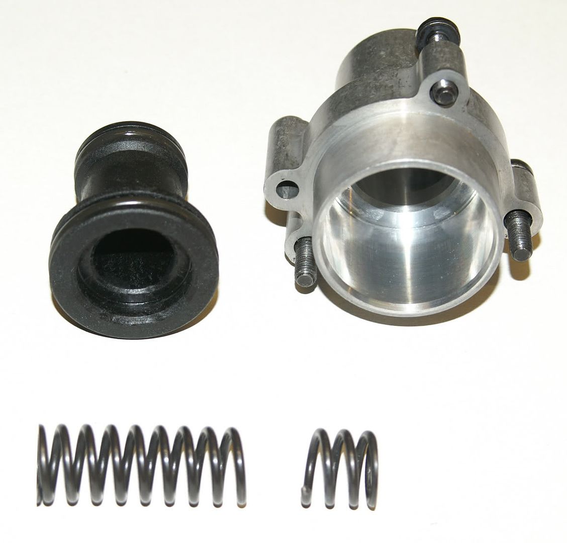
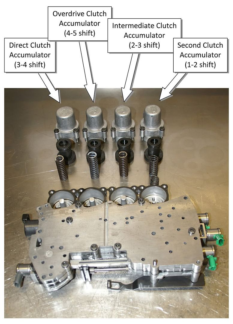 Each is made up of a housing, piston & spring. The ATSG manual states that all four accumulators are identical but this is clearly not the case for the L322 (Range Rover) version of the 5L40-E. Three of the housings/pistons are identical (overdrive, intermediate and 2nd clutch) but the direct clutch accumulator has a larger diameter upper piston & therefore housing. The springs arent all the same either. The overdrive & 2nd clutch accumulator springs are both identical but are longer (65mm measured free length) than the direct & intermediate clutch accumulator springs (60mm measured free length) which, again, appear to be both identical.
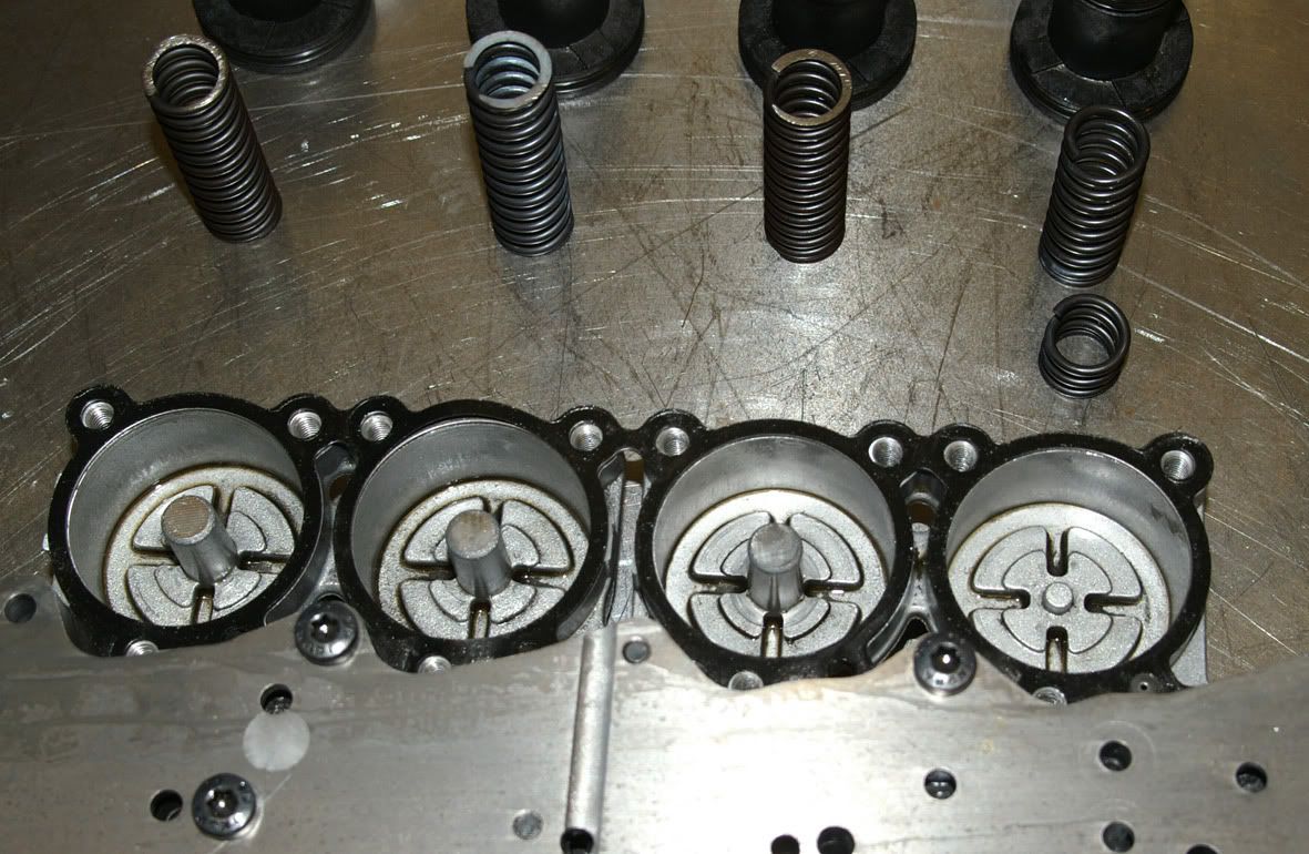
The photos show that the 2nd clutch accumulator spring was broken in my transmission, which must have affected the quality of the 1-2 upshift (I believe that this is quite a common complaint).
Each is made up of a housing, piston & spring. The ATSG manual states that all four accumulators are identical but this is clearly not the case for the L322 (Range Rover) version of the 5L40-E. Three of the housings/pistons are identical (overdrive, intermediate and 2nd clutch) but the direct clutch accumulator has a larger diameter upper piston & therefore housing. The springs arent all the same either. The overdrive & 2nd clutch accumulator springs are both identical but are longer (65mm measured free length) than the direct & intermediate clutch accumulator springs (60mm measured free length) which, again, appear to be both identical.
The photos show that the 2nd clutch accumulator spring was broken in my transmission, which must have affected the quality of the 1-2 upshift (I believe that this is quite a common complaint).
 Interestingly this is the only spring of the four which doesnt have a central support cast into the valve block
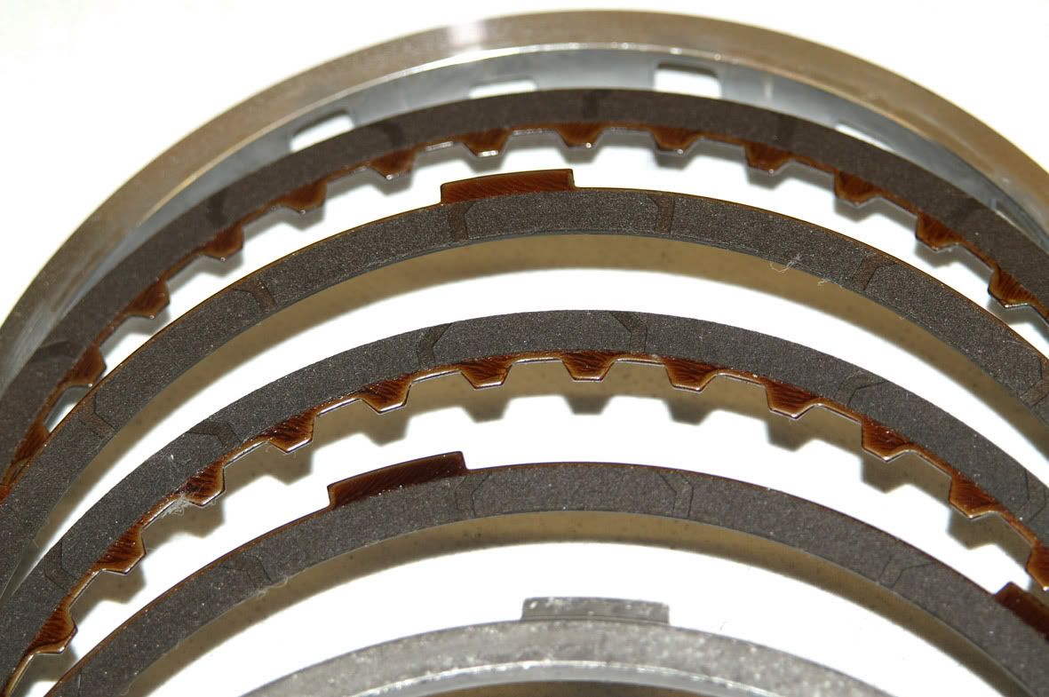
 This particular transmission has the larger diameter second & second coast clutches used in the later models of the 5L40-E :
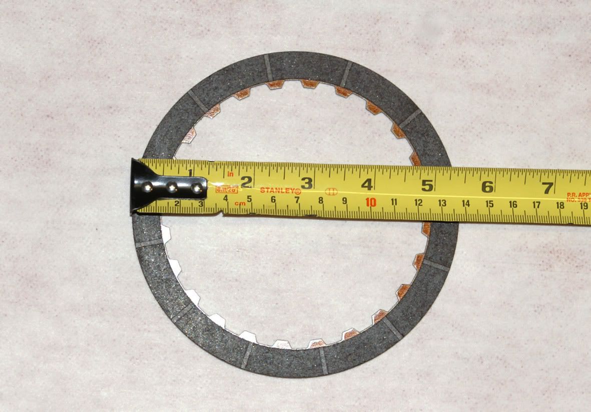 2nd clutch plate outside diameter increased from 130mm in the early models to 138mm
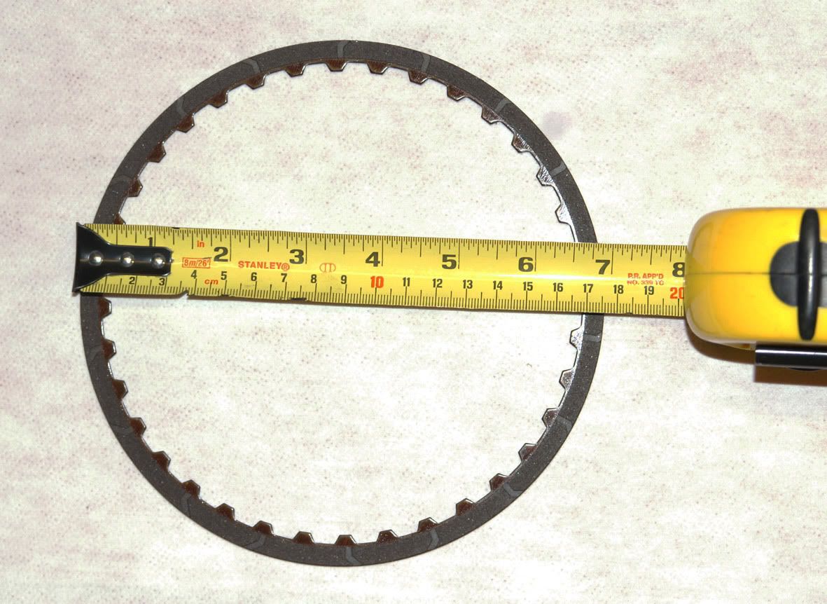 2nd coast clutch plate outside diameter increased from 173mm in the early models to 176mm
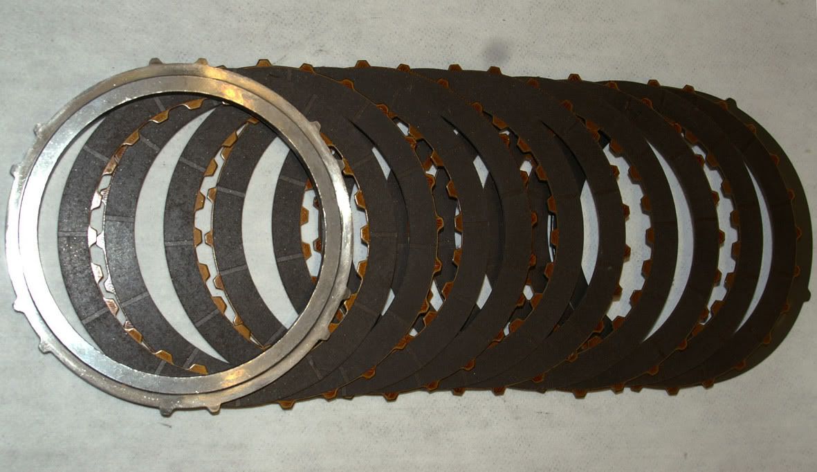
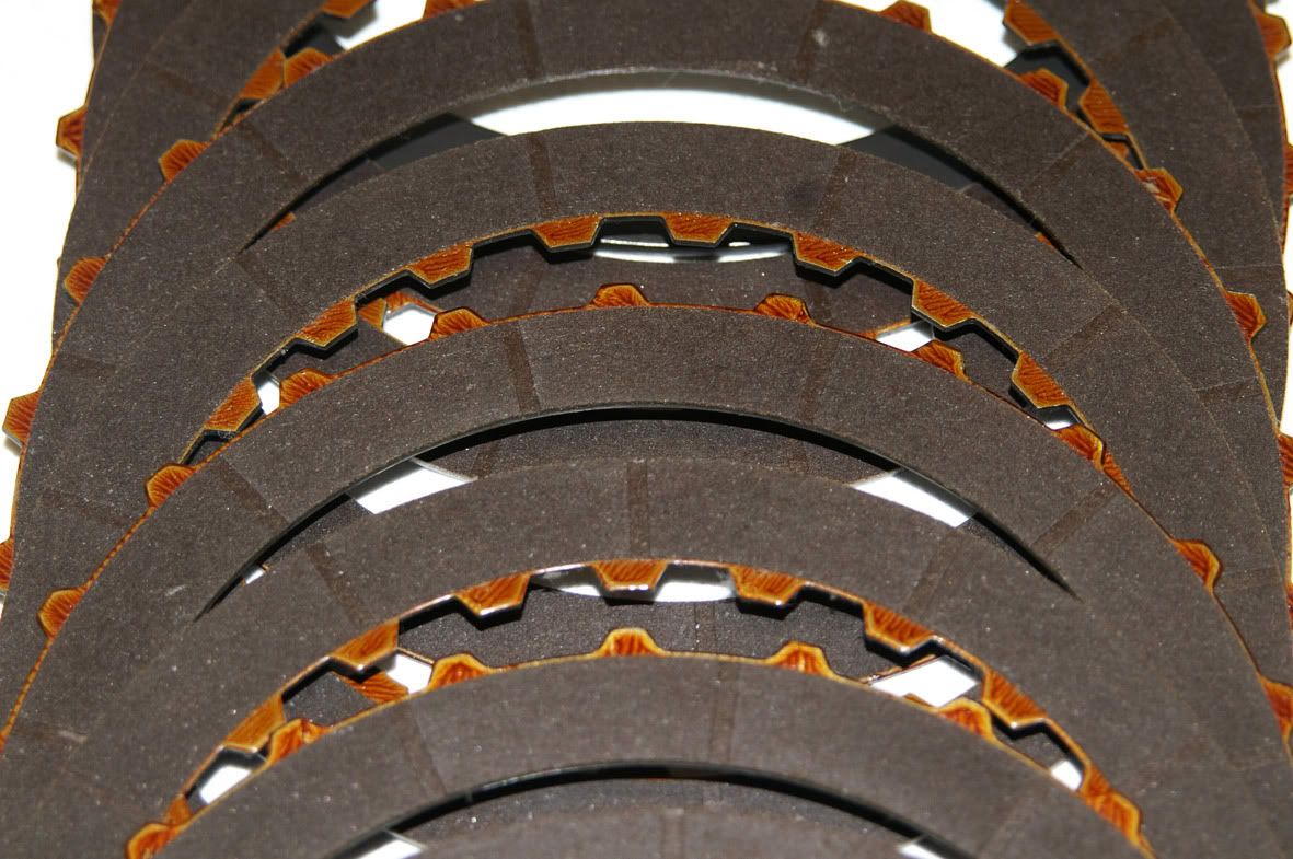
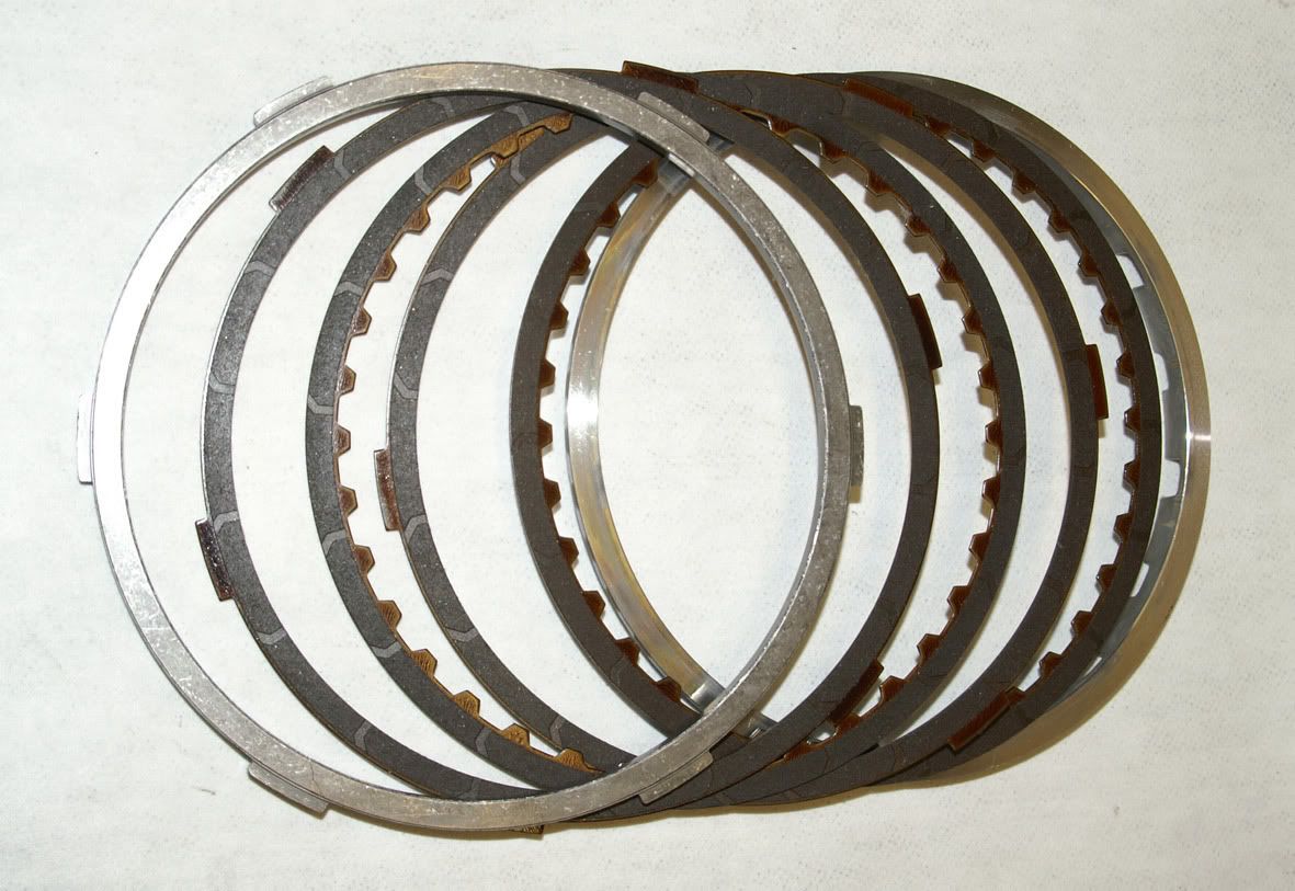
Anyway, the second & second coast clutches were in fine condition :
2nd coast clutch plate outside diameter increased from 173mm in the early models to 176mm
Anyway, the second & second coast clutches were in fine condition :
 Back to the valve block, the seven Torx T30 headed screws are removed from the top channel plate
 Followed by the remaining three screws (2 x Torx T30 and 1-off 10mm A/F, which bolts down the detent spring on the rear valve body) on the control valve body side
 Both the control valve bodies can then be lifted away from the channel plates
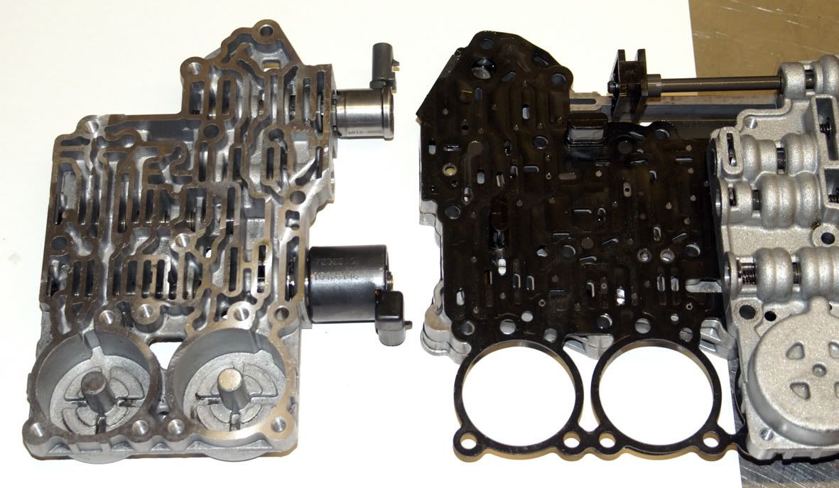
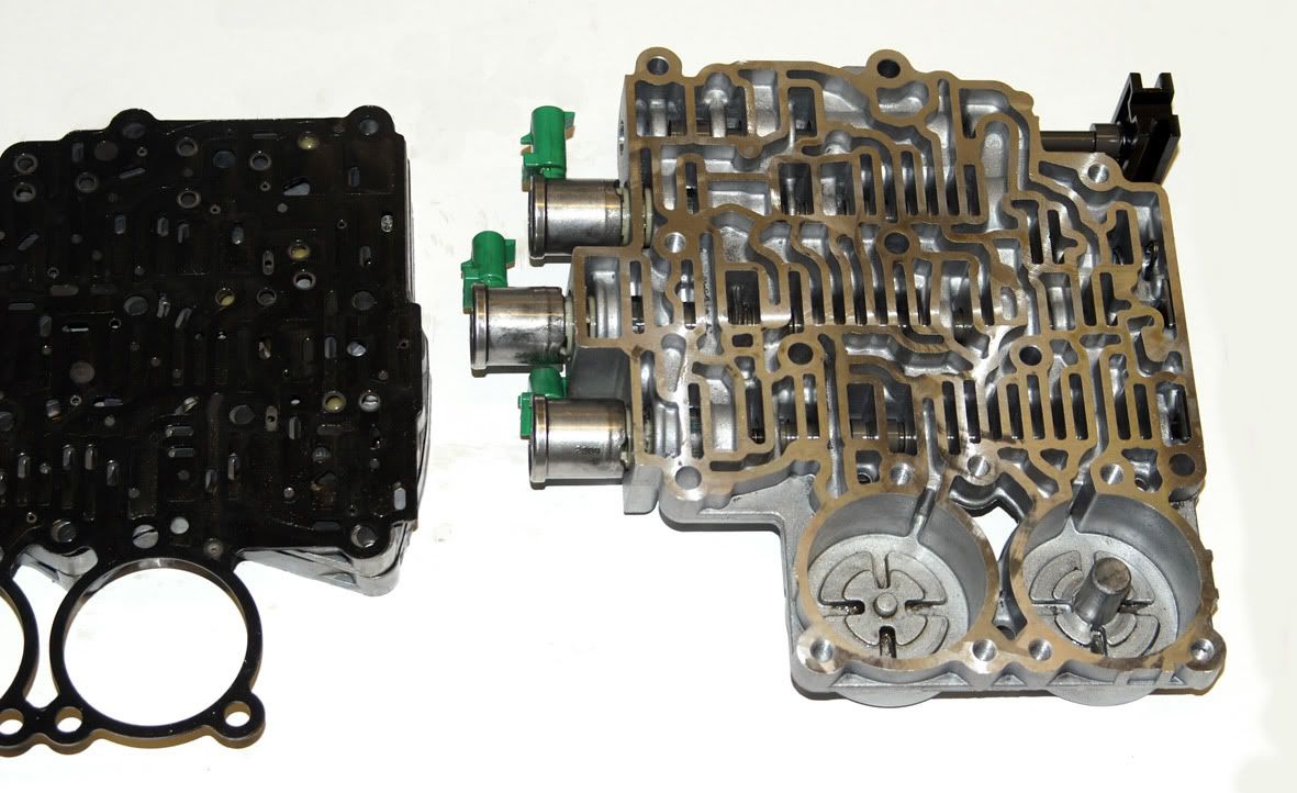 exposing the gasket which seals the control valve bodies to the spacer plate.
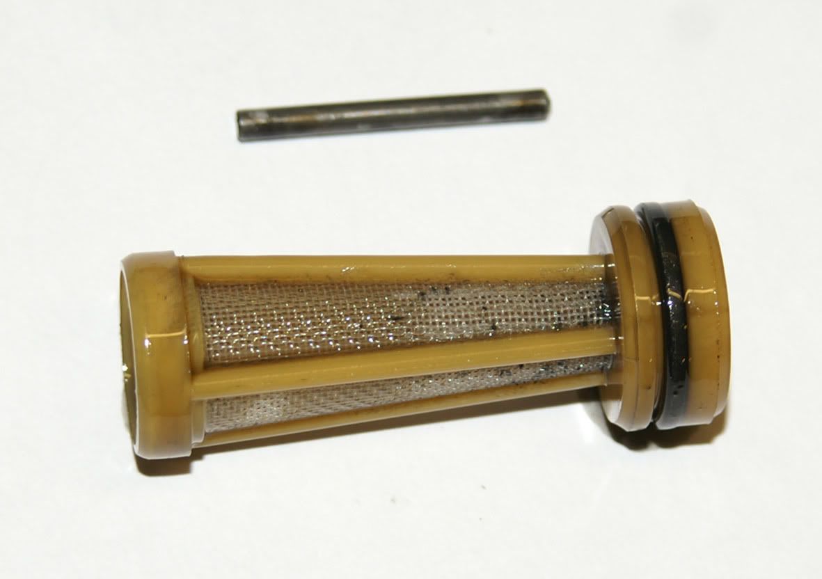
 This gasket is fitted with two screens or filters. One screen is situated between the feed limit valve and the main pressure control solenoid and the other between the feed limit valve and the torque converter lock-up clutch solenoid (the feed limit valve caps the pressure seen by the solenoids to prevent them being overloaded).
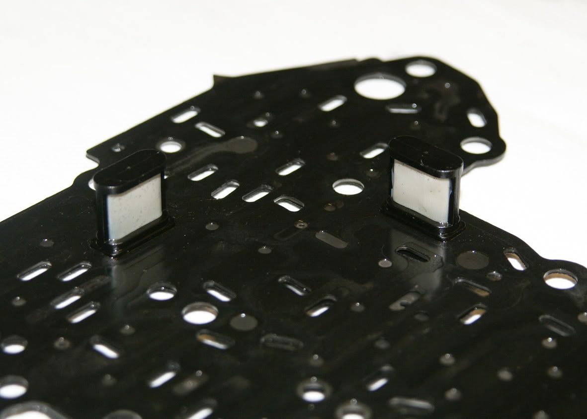 Considering the amount of metallic debris that I found in the fluid these filters are amazingly clean.
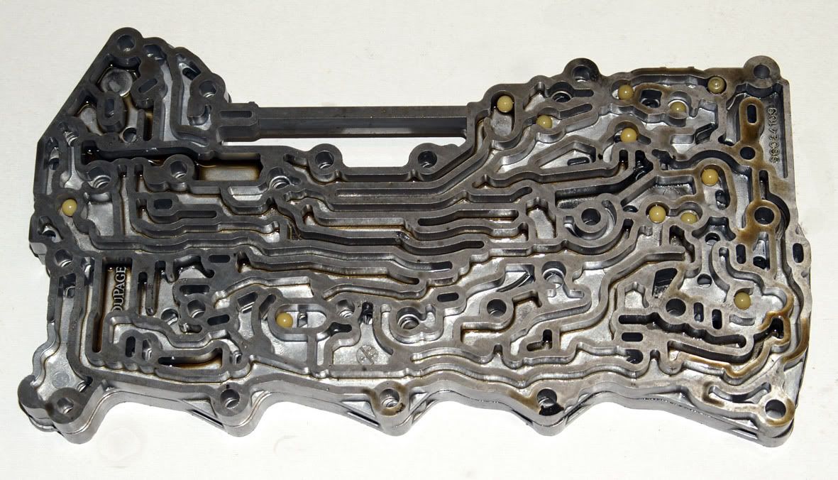
Once the spacer plate & gasket are removed the bottom channel plate can be seen with its twelve ball valves. Everything still looking okay so far........
Considering the amount of metallic debris that I found in the fluid these filters are amazingly clean.
Once the spacer plate & gasket are removed the bottom channel plate can be seen with its twelve ball valves. Everything still looking okay so far........
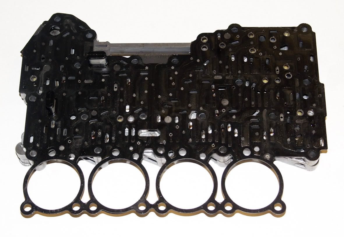
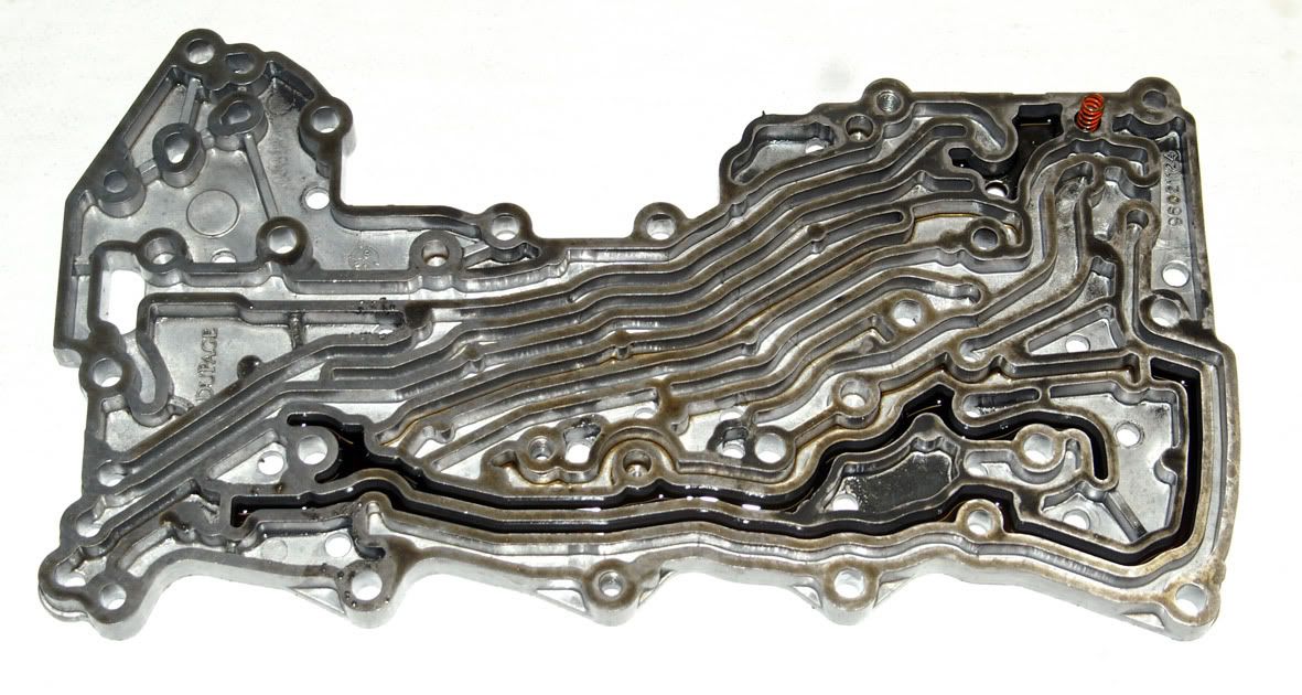
 The top & bottom channel plates can then be separated (yet another gasket)
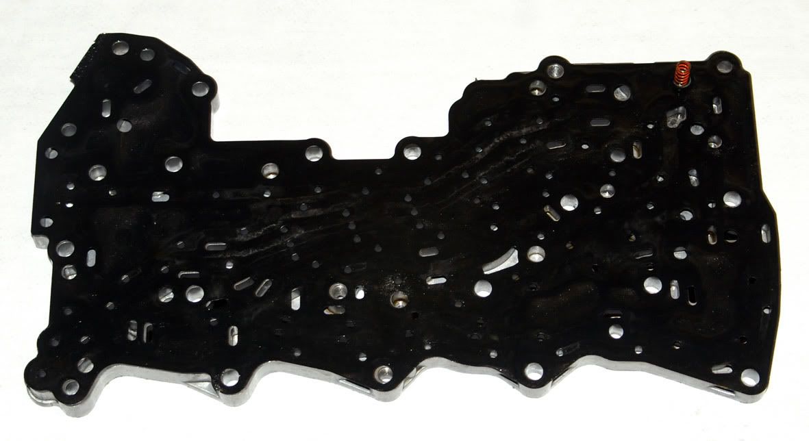 Removing the gasket leaves just the top channel plate
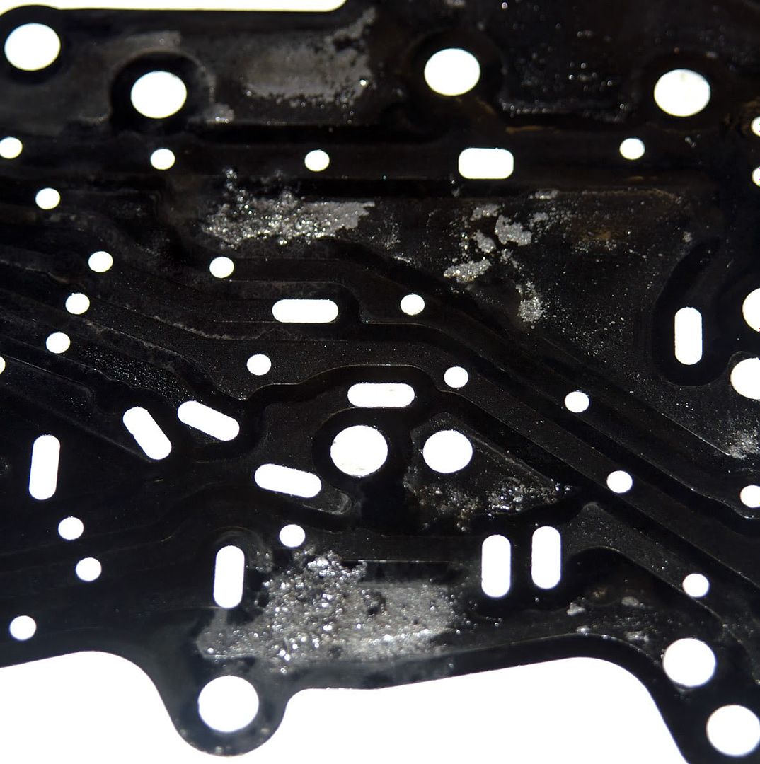
 On the top side of the gasket an amount of metallic debris has accumulated
 So, still nothing much yet to explain the failure. Front & rear control valve bodies next..........
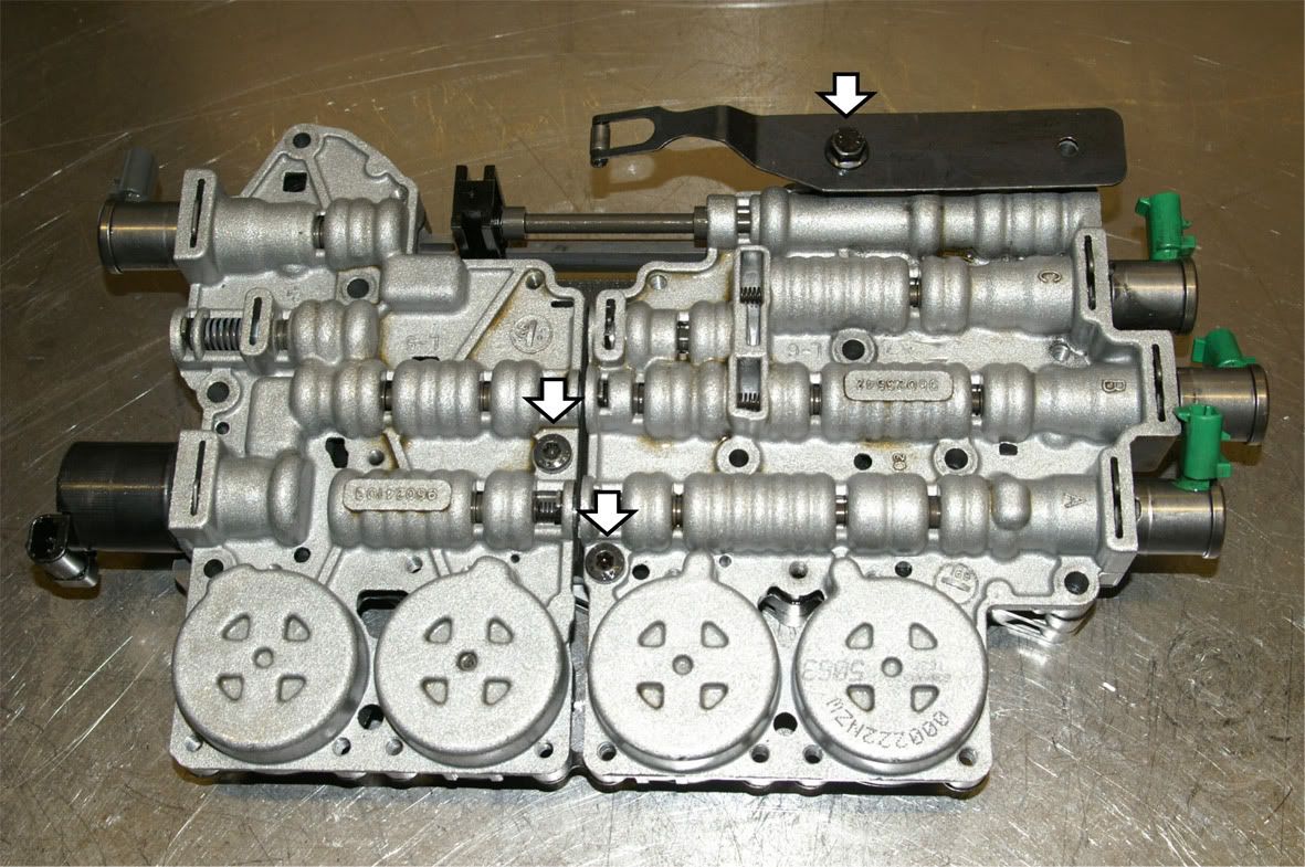
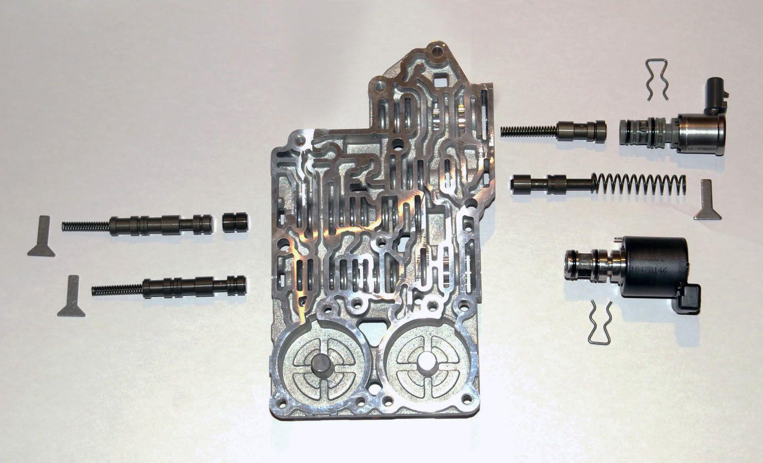
All the valves from the front control valve body :
So, still nothing much yet to explain the failure. Front & rear control valve bodies next..........
All the valves from the front control valve body :
 and the rear control valve body :
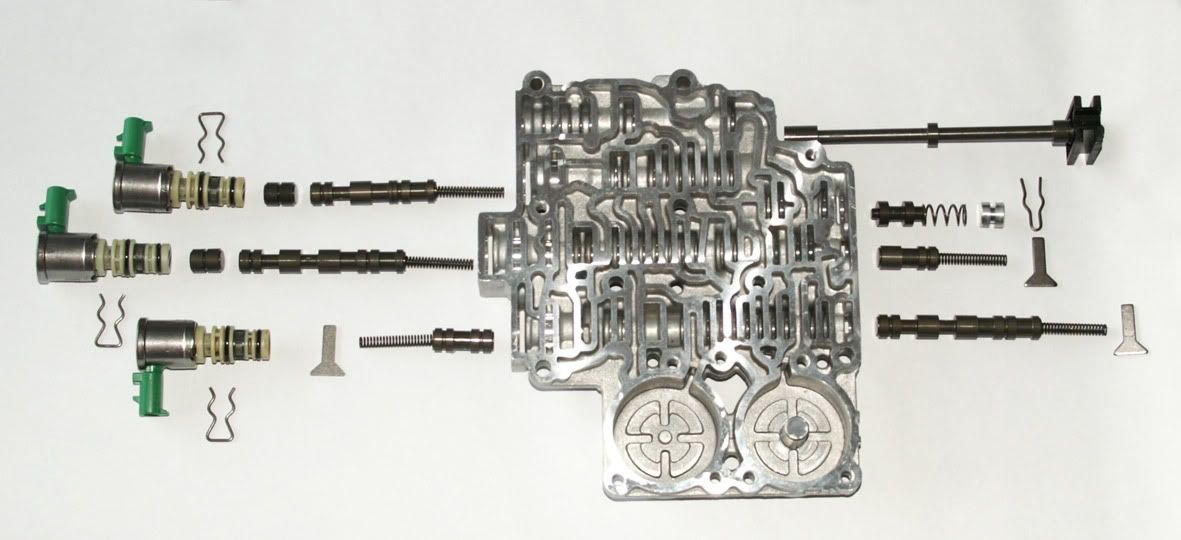 appear, on the face of it, to be fine from just a visual inspection though each would need vacuum testing to properly check the wear levels.
The reverse lockout valve (2nd up from the bottom on the right in the picture above) seemed free to move. This is the spool that commonly sticks and prevents reverse gear from engaging (also see killcraps post above).
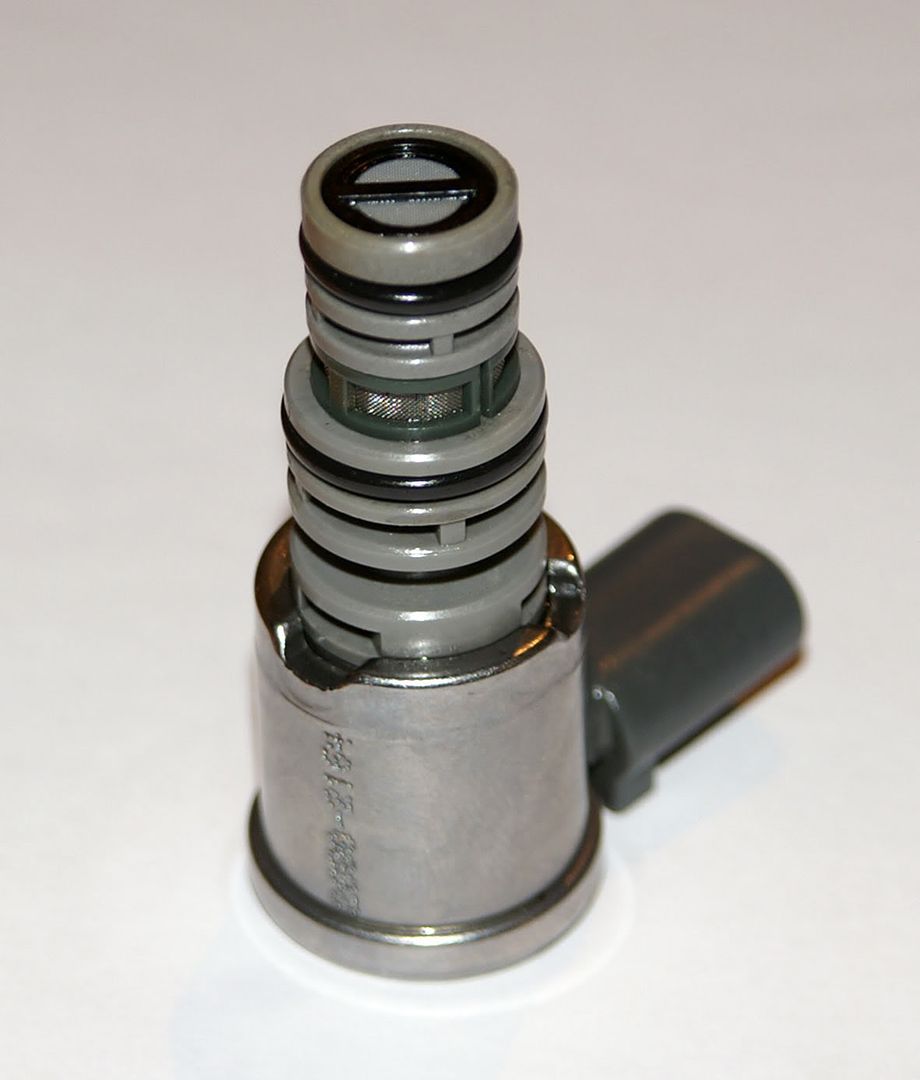
Despite the levels of metallic debris in the fluid it would seem that the filter had still been doing a sterling job of keeping it away from the solenoids which showed no signs of debris around their own screens :
appear, on the face of it, to be fine from just a visual inspection though each would need vacuum testing to properly check the wear levels.
The reverse lockout valve (2nd up from the bottom on the right in the picture above) seemed free to move. This is the spool that commonly sticks and prevents reverse gear from engaging (also see killcraps post above).
Despite the levels of metallic debris in the fluid it would seem that the filter had still been doing a sterling job of keeping it away from the solenoids which showed no signs of debris around their own screens :
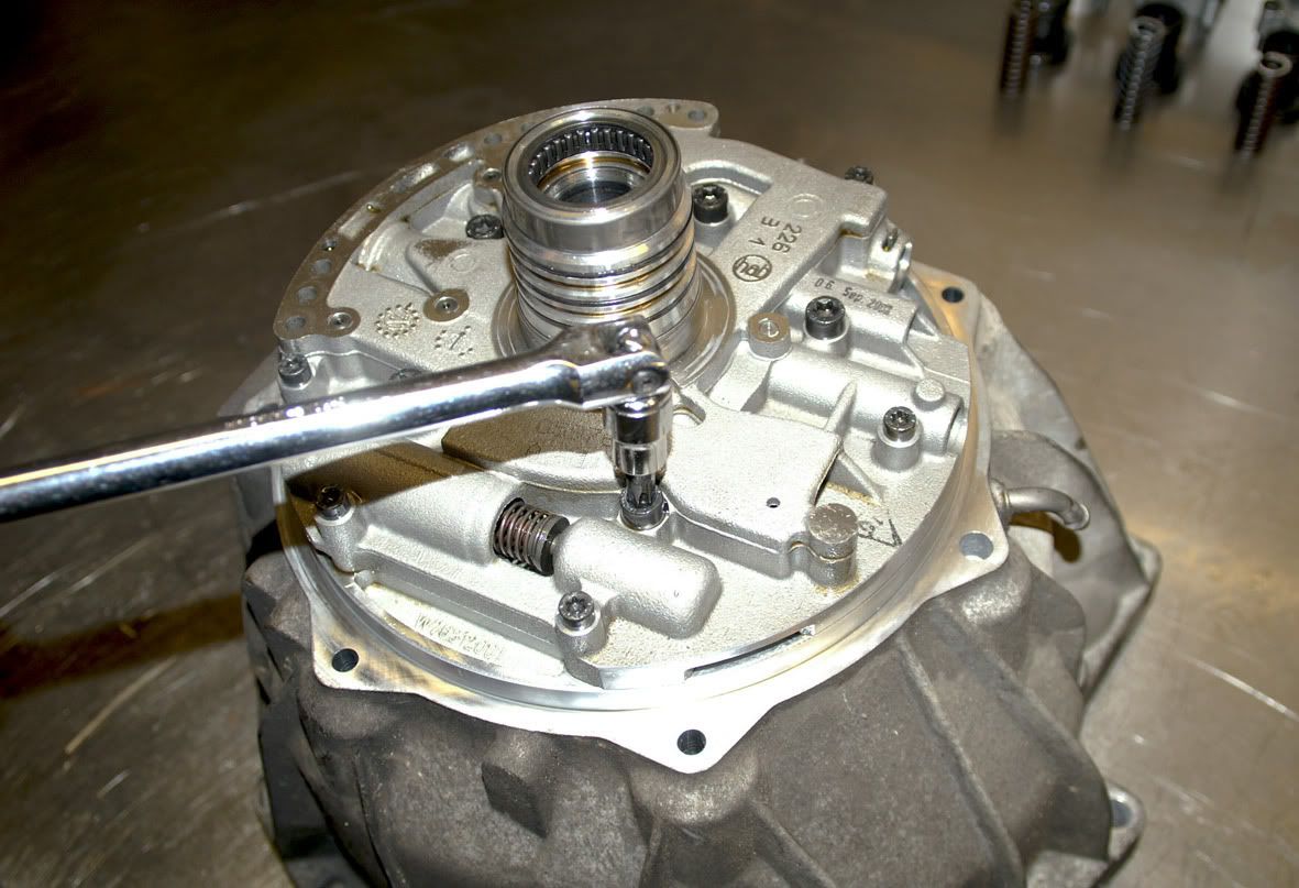
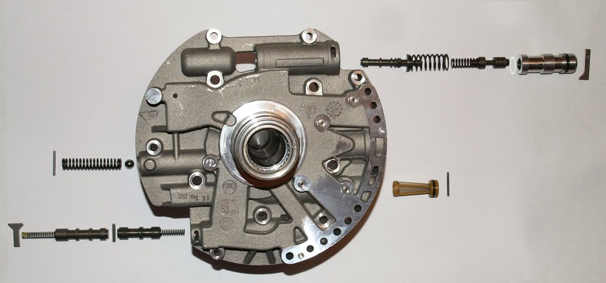
 To check the remaining spool valves I removed the pump cover from the bellhousing :
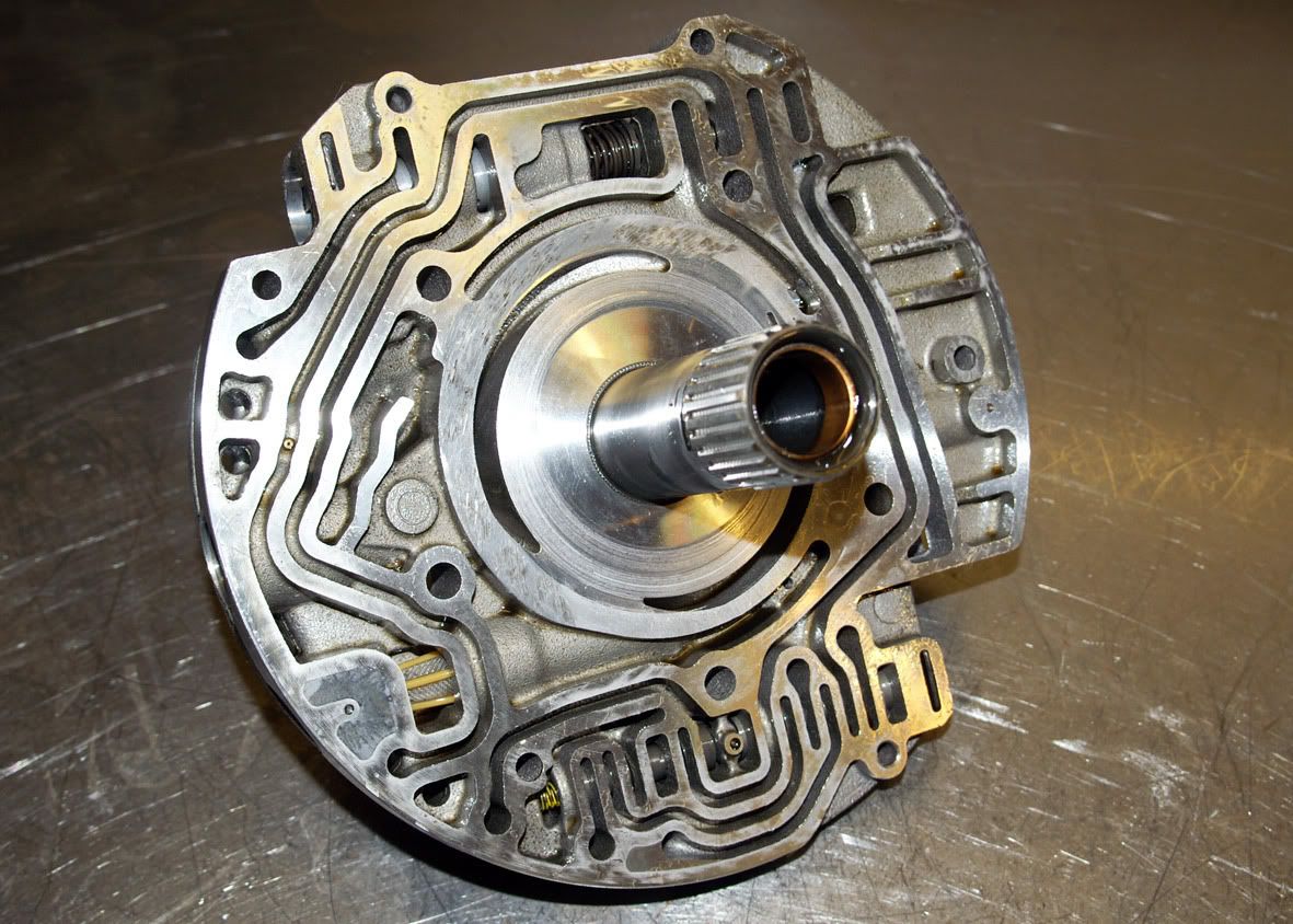 and, again, each spool and valve assembly looks okay visually :
 The main flow screen from the pump :
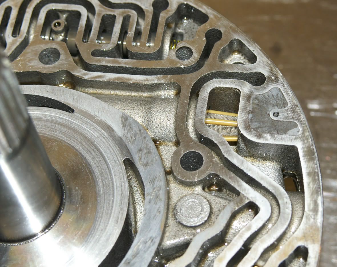 shows no indication that large particles of metallic debris had reached that far into the hydraulic circuit either
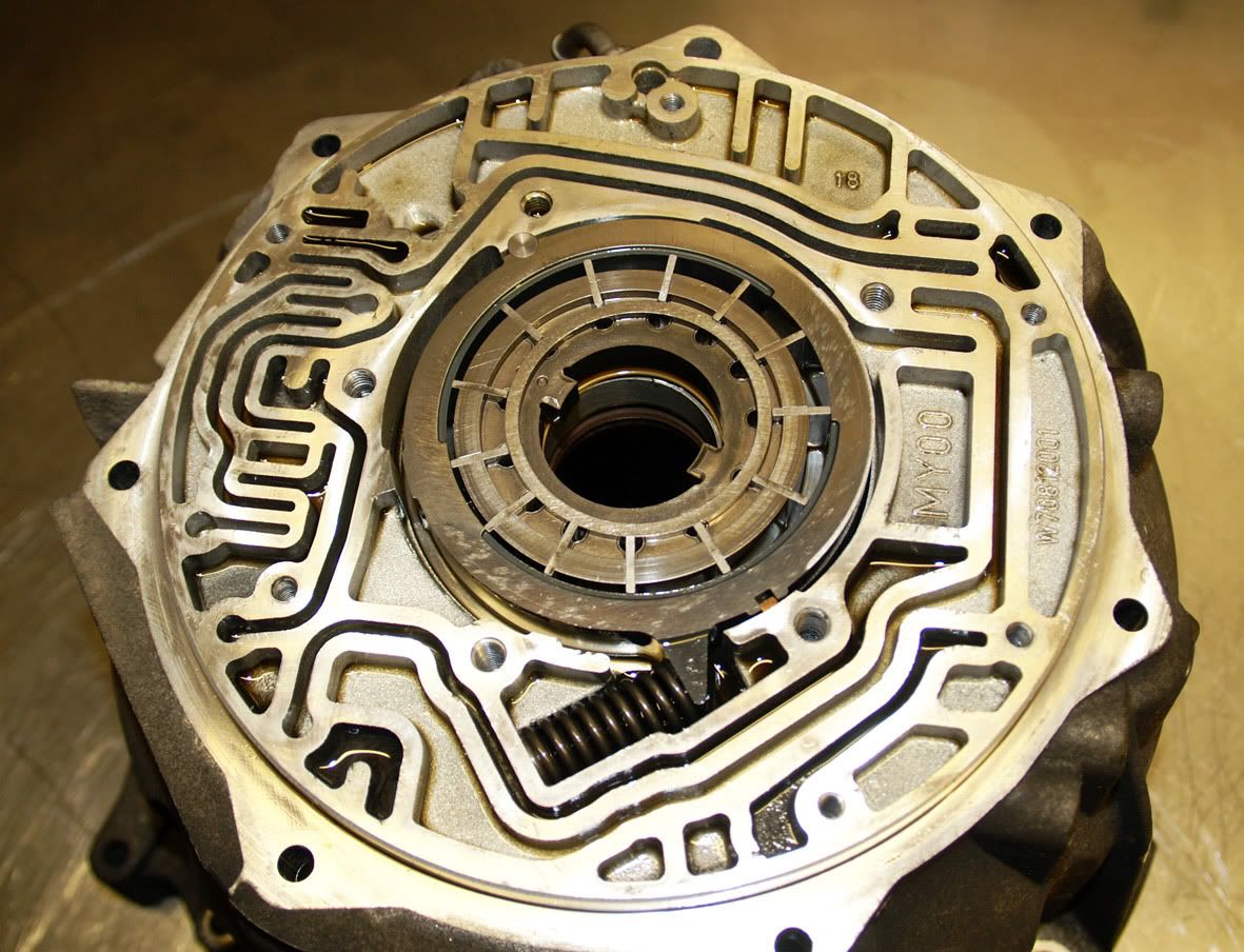
 The pump itself (variable displacement vane-type) also looks in good condition :
 So, in conclusion, all a bit of an anti-climax really. At the start of the teardown I was expecting to find a really obvious cause for the melted clutch packs and the torque converter lock-up clutch which had worn through its lining maybe a stuck valve or, at the very least, something palpable to explain why the transmission had come to such a sticky end but, in the end, nothing particularly stood out.
I would therefore certainly agree with the conclusion that Stevemfr (over on the rangerover.net forum) reached following his research on this transmission i.e. the mechanical problems are the result of reduced hydraulic pressures caused by wear & subsequent leakage in the hydraulic valve blocks. Its unfortunate that I dont have the necessary flow kit to be able to measure the valve leakages and prove this but nevertheless I think that it provides the best explanation.
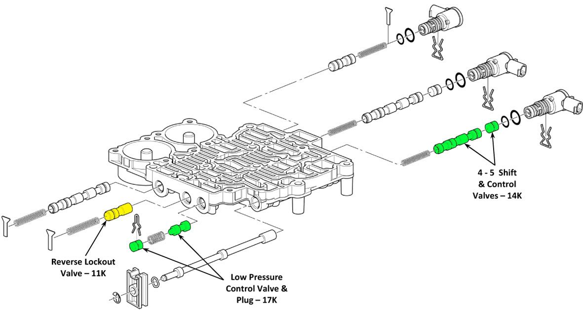
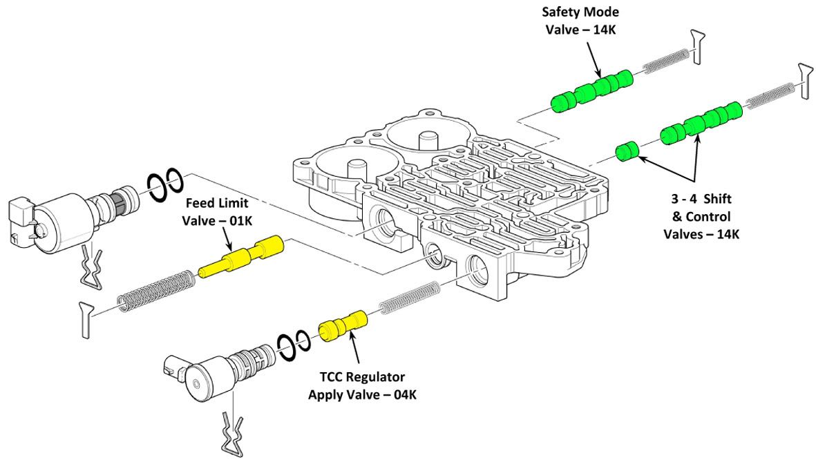
As part of his research Stevemfr spoke to Sonnax - based in Bellows Falls, Vermont, USA - who produce rectification kits for the 5L40-E (as well as many other automatic transmissions) which, they claim, overcome the deficiencies of the soft GM valve blocks. The diagrams below show the individual valves for which Sonnax provide a modification kit. All the spools/valves reside in one of three hydraulic blocks (i.e. front control valve body, rear control valve body and oil pump cover). The spools highlighted in green just require the existing bore to be reamed out slightly larger and then an oversized spool valve is fitted. The spools highlighted in yellow require the bores to be opened out still further so that both a new sleeve and spool can be fitted. The XXK number (e.g. 04K) on the diagrams is the Sonnax kit reference for that particular valve.
So, in conclusion, all a bit of an anti-climax really. At the start of the teardown I was expecting to find a really obvious cause for the melted clutch packs and the torque converter lock-up clutch which had worn through its lining maybe a stuck valve or, at the very least, something palpable to explain why the transmission had come to such a sticky end but, in the end, nothing particularly stood out.
I would therefore certainly agree with the conclusion that Stevemfr (over on the rangerover.net forum) reached following his research on this transmission i.e. the mechanical problems are the result of reduced hydraulic pressures caused by wear & subsequent leakage in the hydraulic valve blocks. Its unfortunate that I dont have the necessary flow kit to be able to measure the valve leakages and prove this but nevertheless I think that it provides the best explanation.
As part of his research Stevemfr spoke to Sonnax - based in Bellows Falls, Vermont, USA - who produce rectification kits for the 5L40-E (as well as many other automatic transmissions) which, they claim, overcome the deficiencies of the soft GM valve blocks. The diagrams below show the individual valves for which Sonnax provide a modification kit. All the spools/valves reside in one of three hydraulic blocks (i.e. front control valve body, rear control valve body and oil pump cover). The spools highlighted in green just require the existing bore to be reamed out slightly larger and then an oversized spool valve is fitted. The spools highlighted in yellow require the bores to be opened out still further so that both a new sleeve and spool can be fitted. The XXK number (e.g. 04K) on the diagrams is the Sonnax kit reference for that particular valve.
 To be able to carry out the re-machining of the blocks an amount of dedicated tooling is required from Sonnax. This consists of a reaming fixture and pump base plate (which can be seen in this YouTube video http://www.youtube.com/watch?v=cWBiDubWvS4 ) together with reamers, jigs and guide pins which are generally unique to each valve. I made enquiries regarding this kit and, all in, the total cost of this tooling is around £1375.
On top of that there is the cost of the valve kits. Each varies between around £45 and £70 depending on its complexity and, as Sonnax produce a kit for eleven out of the fifteen valves, this totals up at just under £600 for all eleven valves to be replaced.
Not, then, a job for an amateur doing a one-off overhaul - but worthwhile, I think, looking out for suppliers who will provide exchange valve blocks with the Sonnax modifications carried out.
Phil
To be able to carry out the re-machining of the blocks an amount of dedicated tooling is required from Sonnax. This consists of a reaming fixture and pump base plate (which can be seen in this YouTube video http://www.youtube.com/watch?v=cWBiDubWvS4 ) together with reamers, jigs and guide pins which are generally unique to each valve. I made enquiries regarding this kit and, all in, the total cost of this tooling is around £1375.
On top of that there is the cost of the valve kits. Each varies between around £45 and £70 depending on its complexity and, as Sonnax produce a kit for eleven out of the fifteen valves, this totals up at just under £600 for all eleven valves to be replaced.
Not, then, a job for an amateur doing a one-off overhaul - but worthwhile, I think, looking out for suppliers who will provide exchange valve blocks with the Sonnax modifications carried out.
Phil

|