Disclaimer
I searched for DIY pictures with instructions to make this conversion. I didnt find one with both pictures and narrative for an E53 X5. When I did find one with pictures and narrative, it was either in a foreign language or not for a X5. I have utilized existing narrative that I found helpful; many thanks to those who unknowingly made contributions. Before beginning the project, I tried to contact them, as I really wanted more detailed instructions and pictures for my conversion.
This harness is sold by at least one other source, just so you know that route is available to you. I have no intention of selling the harness, but I do think there is nothing inappropriate about providing the DIY instructions for the harness as that door has already been opened. There are instructions out there to build this harness for about half the cost of this harness by using off-the-shelf parts from a broad inventory electronics store (In U.S.-Frys/Radio Shack). I chose BMW parts, as they are available worldwide for those outside N.A. and I knew the parts I purchased would work. (I didnt enjoy doing this, so dont give me any grief!)
The instructions are very detailed compared to what I have seen, but I felt it was best to do so. There are many people with differing levels of capabilities that may want to make this conversion and I spent more time and likely screwed up every possible way -- and a few impossible ways -- without them. The instructions are intended to allow anyone I have ever known with the proper tools to DIY. I am confident you have far more common sense than most or all of them.
I assume you have a set of metric sockets, a ratchet, a set of Torx bits, Phillips screwdrivers and regular screwdrivers. If you dont, dont take this on. I have not included instructions on how to disconnect the negative battery cable. If you cant do that on your own, dont do this. The instructions are meant to be complete, but who knows. I didnt have anyone try a conversion with these instructions and they are from memory.
Be sure to read the instructions from beginning to end. I know you wont do that, neither would I, but it is on all complex directions, so I thought I should throw that in. I expect you will look at all the pictures. I at least do that.
It is imperative to read the entirety of each numbered instruction before beginning that step or there is a much greater chance you will make some of the mistakes I did. I hate anything that is near electrical work and I assume everyone does. I am really enjoying the paddle shift wheel but I still hate electrical work. I am not responsible if anything goes wrong, goes wrong, goes wrong. Use this DIY compilation at your own risk.
I suggest you read the entire list of other posts that will follow this one before you begin the conversion. Im guessing there will be some. Some will surely be worthwhile input, corrections or deletions.
DIY X5 steering wheel conversion to E46 SMG M3 paddle shift wheel.
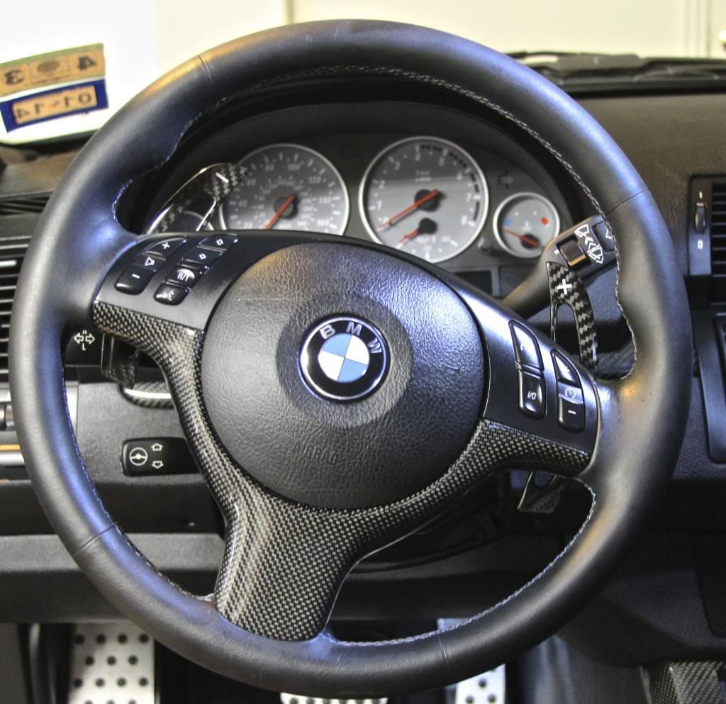
First, check the existing airbag to make sure it is the same shape as needed for the SMG M3 paddle shift steering wheel. If its not, you will need to purchase the proper one. I have a 2002 4.6 (E53) and the airbag is the correct shape. (See the picture of OE steering wheel).
You may need a new wheel steering wheel switch unit (SWSU) check step 12 of conversion. If you need a new SWSU the part number is 61318379091.
New SMG M3 paddle shift steering wheels are available but they are expensive. I found a used one on eBay for $245. I purchased a leather repair kit and filled defects and re-dyed it to like-new. Either way you go, you will need the lower surround trim if it doesnt come with the wheel because the lower steering wheel surround is different on the new SMG M3 paddle shift wheel.
[B]
See step 14 for part numbers for plug and play harness connectors and wires.
The Conversion
1-Move the drivers side seat as far to the rear as possible. You will need the room.
2-Disconnect the negative battery cable. This is so you dont cause an airbag fault light or cause it deploy. If for some reason your work causes an airbag fault you can purchase a reset tool to clear it. FYI-Not all code readers will reset the airbag.
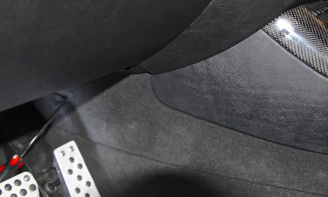
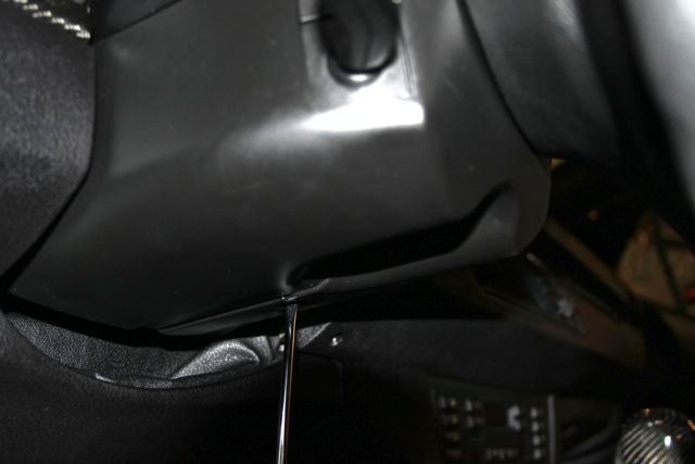
3-Remove the forward most carpeted trim under the dash on the side and below the console. There is one screw holding it in. Once you have removed the screw, use a screwdriver to pop the press tabs free from the bottom of the trim until you can carefully pull the center of the trim outward. The rear portion of the trim will come out from under the rear trim piece when you bend it enough and pull forward. Set the trim aside
 4-
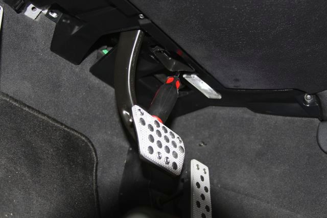
4-Remove the plastic trim piece that circles the brake pedal. There are 3 screws on the side closest to the steering wheel and a twist out toward the engine. Pull the trim piece down as far as it will go. It is not necessary to remove it. Be careful not to dislodge the air/heat vent that exits through it. It will go back in but you may have some difficulty getting it to seat properly.
 5-
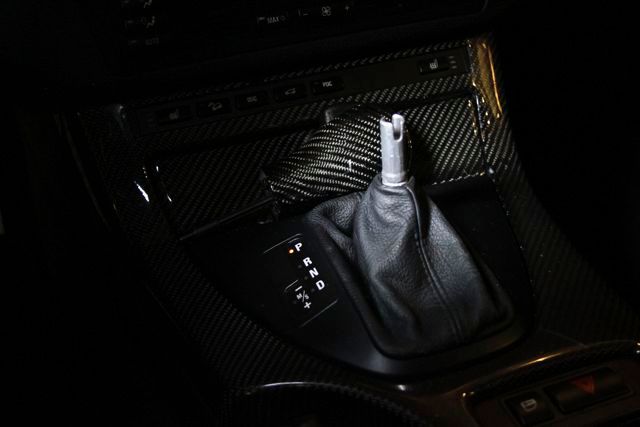
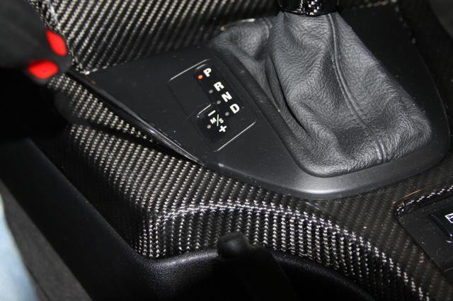
5-Remove the shifter knob by pulling it straight up. You may have to pull harder than you feel comfortable but it will pull out with no damage
 6-
6-With a plastic trim tool -- or very gently with a screwdriver -- pry the back of the shift surround up and pull up on the leather boot at the same time. Be careful not to crack the console. It is not necessary to remove the trim, just let it drape over the passenger side of the console. Now you have access to the shifter electrical connections.
 7-
7-Remove the upper steering column trim piece. There is one screw holding it in place and then it pulls free of the tabs
 8-
8-Remove the lower steering column trim piece. There is one screw, a long one.
 9-
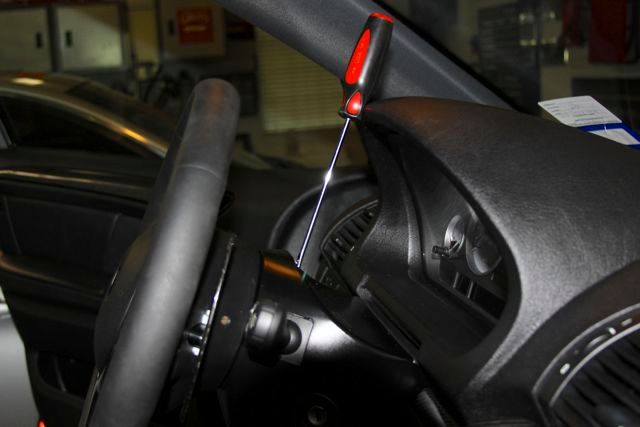
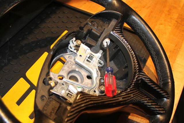
9-Remove the air bag. This can take some time to find the spring retainers. Push a regular screwdriver through the access hole on both sides of the steering wheel. The retainers are toward the floor at about a 90-degree angle. You can tell when you have found the retainer. When you push in you will feel the spring pressure pushing back. When the retainers are pushed in far enough, that side of the airbag will release. Lift the airbag carefully out so you dont damage the wires connected to the back. There are two connections to the airbag. To release the connections, carefully pry up the center of the connector with a small screwdriver. It doesnt take much pressure to release the connector so
be gentle. Once released, just pull them straight out of the back of the airbag.
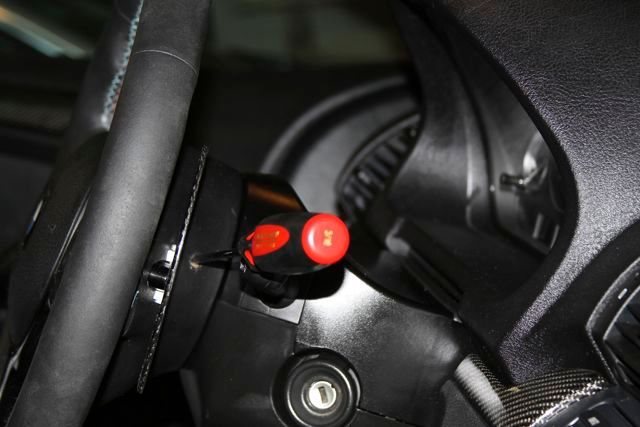
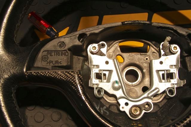
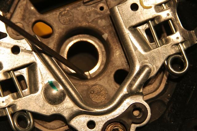
Angle to make contact with spring release
10-Remove the upper steering wheel surround. There are two screws. Once the screws are removed pull it straight out. There are tabs that will release. Be careful not to pull it out too far before you disconnect any connectors
 11-
11-Remove the nut that secures the steering wheel.
I suggest using a breaker bar. Sit so both knees are wedged against the bottom of the wheel and one hand on the top. Use the other hand to pull down on the bar. I dont recommend using an impact gun or using the steering wheel lock to hold the wheel in place. Note the mark on the steering wheel and the corresponding mark on the steering wheel shaft. These are your alignment marks that you will use when you install the new steering wheel.
 12-
12- If you do not have the correct SWSU see also step 13. You need a new steering wheel switch unit (SWSU) if yours doesnt have pins in the two-pin receiver on the front of the switch.
It is best to check this before purchasing a new SWSU. If you are thinking about purchasing it beforehand to minimize downtime, remember it is an electrical part that you may not be able to return. If you purchase a SMG M3 SWSU that you don't need, you may be able to return it if you have not broken off the red tab that needs to be removed to install the unit. I suggest having the option to return established before you purchase the unit. My X5 had the proper SWSU.
13-If you need a SWSU--- Remove the 2 screws holding unit in place and remove the connectors on the back and slide it off the steering wheel shaft
14-To build the plug and play wiring harness you will need the following wires and connectors available from BMW:
2 each red/black wires with pins-male-61130006664
2 each black wires with pins-male-61130005198
3 each red/black wires with receivers-female-61130005197
3 each black wires with receivers- female-61130006663
1 each 4 pin connector-female-61136925611
1 each 4 pin connector-male-61138380696
I each 2 pin connector-male-61136925634
3 feet of compatible red wire
3 feet of compatible black wire
A selection of electrical thermal shrink-wraps. In the U.S. Lowes had just what I needed in a kit.
15-The male and the female connectors will need the proper wires pushed into the connectors. The green female connector uses the wires with the pins. Alternate red/black and Black wires in the four positions on the connector. Do the same on the male connector. The male connector uses the wires with receivers on the end. Match the red/black layout on the female connector. Be sure to have both connectors facing you on the sides that will carry through the combination so that you have the same wire positions through each of the existing purple OE shifting connectors. Insert one red/black wire and one black into the 2-pin connector using the same process you used with the other connector and set it aside.
Note- I am not including the correct colors going into and exiting from the red connectors, as they may be different on some years. Splice the wires together. I used electrical shrink tubes. I didnt use solder, as there is no stress on the wires, your call. Include the one red and the one black compatible wires going to the SWSU with the two center wires in that splice. The 3 wire splices should be between the green four-pin connectors. The distance between the green connectors should be 3-inches. I suggest using 3 feet for the two inside splices that will be spliced to the 2 pin connector wires that control the paddles. If you can, this is a good time to test continuity from the wires going into and out from the red connectors with the harness in place. Check continuity of the paddle shift wires through the 2-pin connector as well.
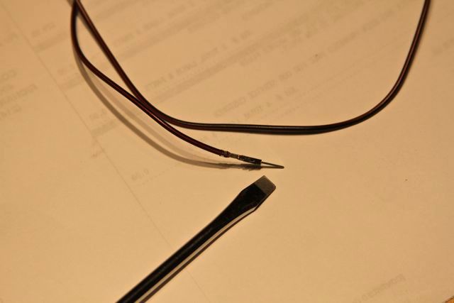
Wire with pin
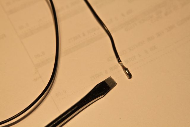
Wire with receptacle
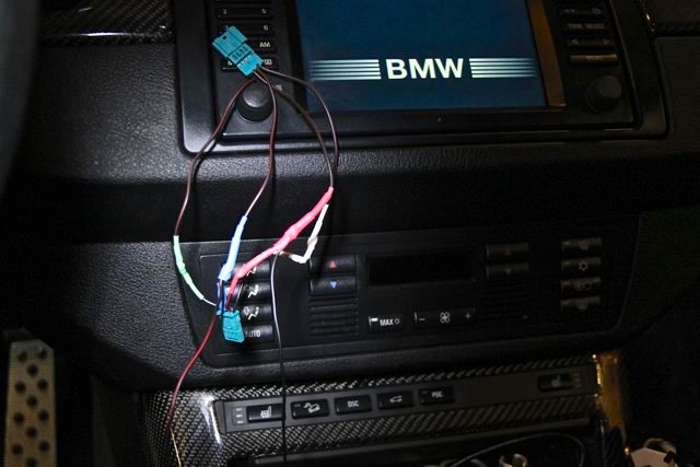
Competed harness. Note the 2 wires at the bottom of the picture that go to the steering wheel. Those are two wires that are spliced between the two new connectors.
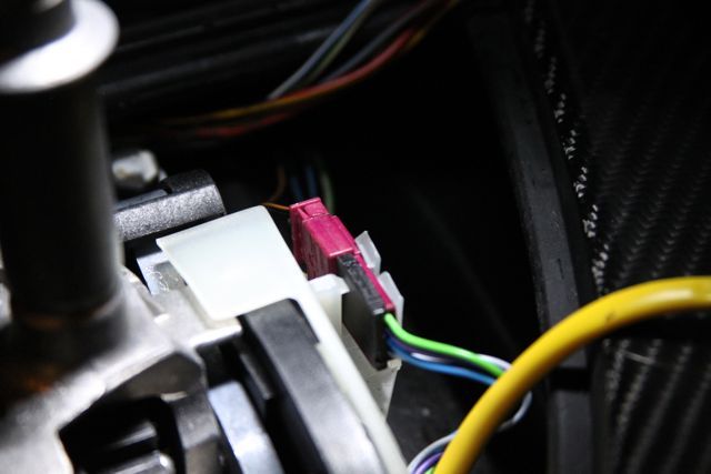
Location of OE shifting connection.
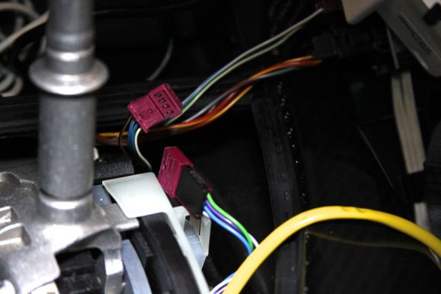
OE connection separated for new harness install.
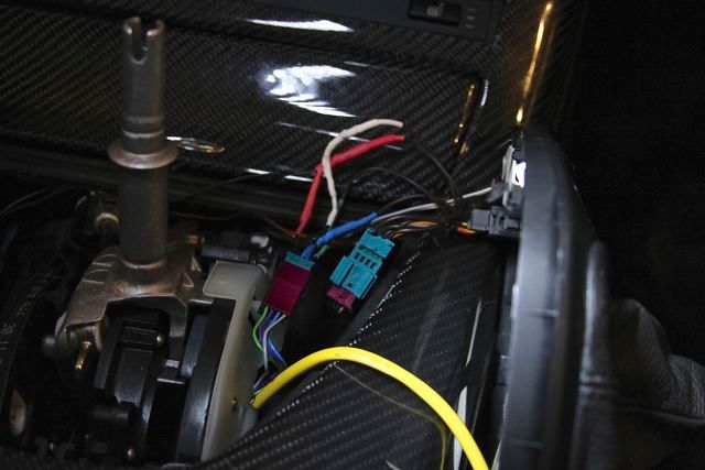
Harness installed.
16-Optional step-Since I couldnt be sure the 2-pin connector was wired properly for up/down shifts, I tested the harness. To test your harness, plug the green 4-pin connectors to the red existing connectors. Route the two wires that go to the steering wheel unit, cut any excess and
twist the 2-prong connector wires to the wires coming from the harness. Make sure they dont touch the other during the test.
Noteroute the two wires around the backside of the shifter and run inside the console bracket and then down until you can reach them to complete the routing. The wires run behind the side trim and above the plastic trim piece.
Install the correct SWSU. Tighten the 2 screws. Plug in the connectors on the back of the unit. Align the center of the metal part of the unit with the steering shaft mark. If aligned properly the raised part of the unit that fits into the gap in the steering wheel will be centered in the slot.
Set the new steering wheel in place. Take your time with alignment. It takes some pressure to get the steering wheel to slide on. Be careful not to damage the splines on the steering shaft. There is a washer that is on the steering wheel shaft that sits on a ledge. Dont bother trying to get it in the right place. When you push on the steering wheel it will fall into place.
It is not necessary to put the nut on at this time. When assembled properly the marks on the steering wheel, steering shaft and the center of the metal piece on SWSU will all align. If not aligned properly the DSC light will come on after turning the wheel lock to lock several times with the engine running. Press in the upper steering wheel surround. It is not necessary to screw it down.
Connect all the connectors that go from the steering wheel surround and the paddles to the front of the SWSU. Connect the wires to the air bag. It is not necessary press in the airbag. Connect the negative battery cable.
To test just the wiring, turn the key to the second stop. Move the shifter to drive and then to manual. Shift up and down with the shifter so you know the manual is working then use the paddles. Moving to higher gears is the plus side on the right. Once the paddles work properly finish the 2-wire splice.
You can also verify the steering wheel switch unit is in the proper position at this time iby running the engine and turning the wheel lock to lock several times and see if the DSC light comes on. If the light comes on remove the steering wheel and re-align the steering wheel, start the engine, turn the wheel lock to lock several times and the light should go out. If you dont do the test and alignment is incorrect it will be necessary to tear it down again after you have completed the conversion.
When you have completed the testing disconnect the negative battery cable. Disconnect and remove the air bag and the upper surround.
17-Install the correct SWSU. Tighten the 2 screws. Plug in the connectors on the back of the unit. Align the center of the metal part of the unit with the steering shaft mark. If aligned properly the raised part of the unit that fits into the gap in the steering wheel will be centered in the slot.
18-Set the new steering wheel in place. Take your time with alignment. It takes some pressure to get the steering wheel to slide on. Be careful not to damage the splines on the steering shaft. There is a washer that is on the steering wheel shaft that sits on a ledge. Dont bother trying to get it in the right place. When you push on the steering wheel it will fall into place.
19-Secure the steering wheel nut. Torque to 46-48 ft./lbs.
20-Press the lower steering wheel surround in place and install screw.
21-Push the upper steering wheel surround in place, push in the connectors from the surround and the paddles into the SWSU. Install the two screws.
22-Pull the locks on airbag connectors up and push the connections on and then push the locks down. Snap the airbag into place.
23-Plug in all the connectors that go into the back of the SWSU including the new 2 prong connector.
24-With the upper steering wheel trim in place, install the screw.
25-Snap the lower rim inside the upper trim and install the long screw.
26-Attach the 3 screws and the twist screw on the plastic trim piece under the dash, making sure the new wires are above the trim and being careful not to disturb the air/heat vent. The plastic piece seats in the crease you can see in your carpet.
27-Work the carpeted side until it is almost in place. Bend the trim toward you until you can slide the rear lip under the rear trim piece. Push the trim in place then attach the screw. Be sure the paddle wires up out of the way so they dont get pinched.
28-Snap the cover for the shifter into place
29-Push shift knob on